High speed PCB material Selection Guideline
For proper stackup selection for high speed signals in your PCB layout, follow these guidelines:
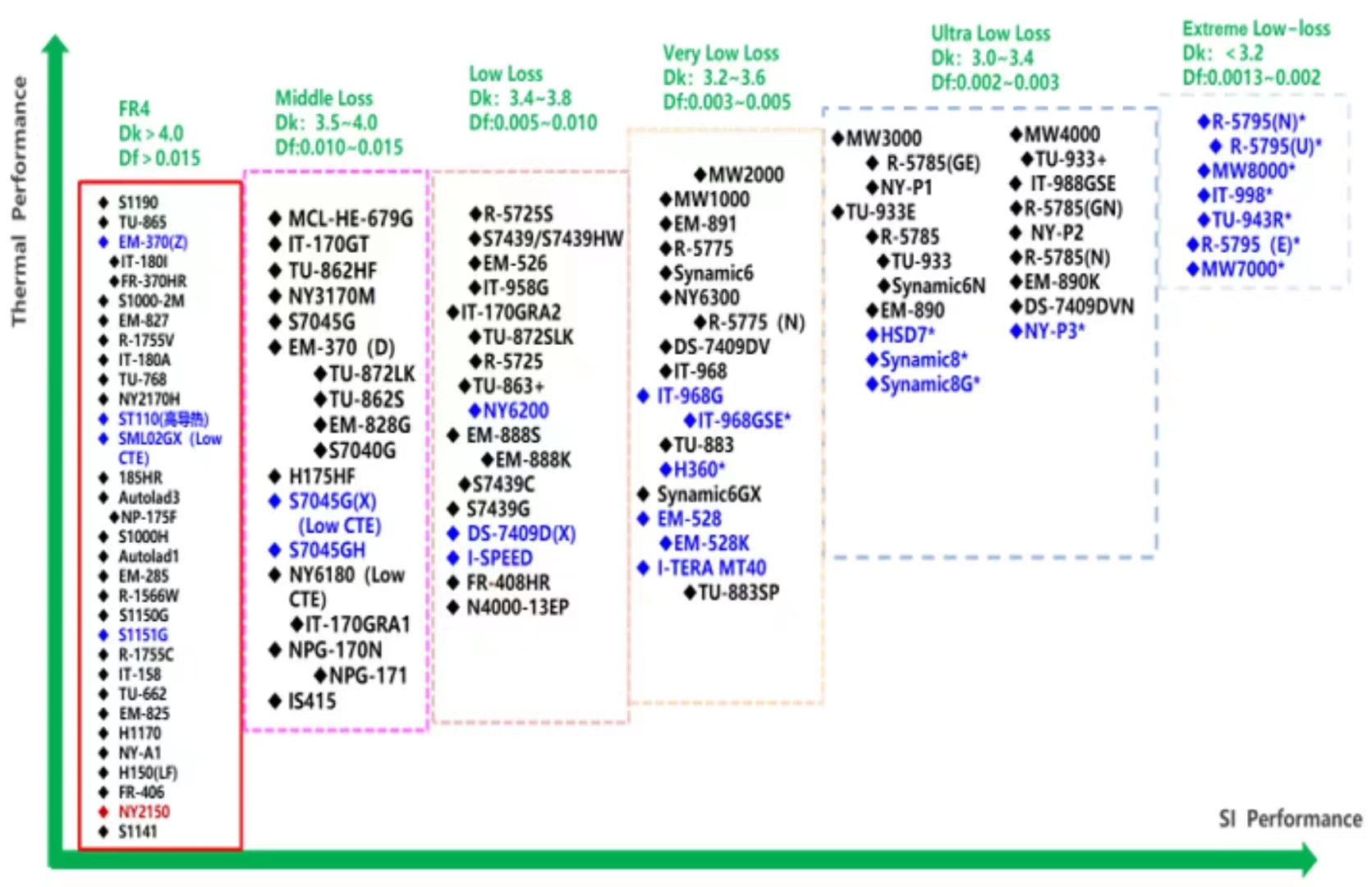
- Select a dielectric material with the lowest loss tangent and smaller dielectric constant, for example, the Megtron6 (df<0.002, epsr=3.1) is an appropriate choice.
- When they become available after vendor characterization, dielectric materials such as Megtron 6N/6G or Tachyan 100G are good selections.
- 25+G designs require special attention to material details including Fiberglass, Dielectric Matrix and Copper. The signal at higher data rate has higher frequency element and the wavelength goes on reducing. The change of fiber glass pattern, dielectric matrix pattern and copper pattern should be considered carefully. As for higher data rate (shorter signal wavelength), it appears to create more discontinuities and reflection with slight change. Please refer to PCB Dielectric Material Selection and Fiber Weave Effect on High-Speed Channel Routing for more information.
- Select smaller dielectric height for high speed signal routing.
- It requires smaller trace width for trace impedance target. There is always a trade off between selecting wider trace width and shorter trace width. The wider width has less skin depth and lower insertion loss but takes more space for routing.
- It also results in a smaller PCB height as well as smaller transition via height for achieving minimum impedance mismatching.
- Select enough stripline layers for all critical high speed signal routing.
- Hemeixin recommends stripline routing for all critical high speed signals (above 15 Gbps).
- You can route all non-critical high speed signals (below 15 Gbps) on a microstrip layer.
- Stripline routing has maximum isolation with other layers as long as both sides are reference planes. Hemeixin does not recommend dual stripline routing unless the signal routing on both stripline layers are perpendicular. This means, longitudinal broadside coupling of differential pairs should be avoided.
- Hemeixin recommends Stripline preferred over microstrip. If microstrip routing is selected, Hemeixin recommends removing the solder mask.
- Stripline routing requires smaller trace width, which results in more space for signal routing.
- Selection of a ground/signal/ground stackup combination for critical high speed signals.
- Selection of a ground/signal/ground combination may be feasible as long as the signal routing crossings on both stripline layers are perpendicular to minimize broadside coupling which results in cross-talk.
- Select enough power/GND layers to cover the power supply rails.
Below is a comparison chart sorted by Dielectric Constant and Dissipation Factor values. This chart provides the basic properties of the various laminates available
|
Material |
Relative Permittivity (Real Part) |
Loss Tangent |
|
Typical FR4 |
4 |
0.02 |
|
GETEK |
3.9 |
0.01 |
|
Isola 370HR |
4.17 |
0.016 |
|
Isola FR406 |
4.29 |
0.014 |
|
Isola FR408 |
3.7 |
0.011 |
|
Panasonic Megtron 6 |
3.4 |
0.002 |
|
Nelco 4000-6 |
4.12 |
0.012 |
|
Nelco 4000-13 EP |
3.7 |
0.009 |
|
Nelco 4000-13 EP SI |
3.2 |
0.008 |
|
Rogers 4350B |
3.48 |
0.0037 |

PCB Trace Attenuation Comparison per 1 inch Trace Length for various dielectric materials, while Trace Width is 5 mil, results up to 20 GHz.
From the above figure, Megtron 6 has 0.85 dB average loss per inch at 28 Gbps (Nyquist is 14 GHz). On the other hand, Typical FR4 has approximately 2 dB loss at the same frequency.
Copper thickness has not been encounter into the above approximate PCB attenuation equation. The thicker copper width, the less trace resistance.
Hemeixin recommends that the designers must consider an average of +/-5% variation into the loss obtained in figure PCB Trace Attenuation Comparison per 1” trace length for various dielectric materials, while trace width is 5 mil, results up to 20GHz due to some material tolerances by Fabrication Company.
An average surface roughness (approximately 2 µm) has been included into the approximate PCB attenuation equation for trace loss attenuation. For accurate loss calculation, Hemeixin recommends the designers to have at least 2.5D CAD analysis on transmission loss attenuation considering actual surface roughness, copper thickness and frequency dependent dielectric materials.
| Material | MEG4 | MEG6 | Tachyon100G |
| Average Loss per inch @14 GHz | 1.2 dB | 0.85 dB | 0.8 dB |
Overall, MEG6 and Tachyon100G materials are the best options for 28 Gbps high speed signals routing.
For more information on the various weave compositions and material dielectric loss considerations and their influence on the channel performance, refer to PCB Stackup Design Considerations for Altera FPGAs and PCB Dielectric Material Selection and Fiber Weave Effect on High-SpeedChannel Routing.
Estimating the insertion loss based on selected PCB stackup material
Transmission line has various losses including the conductor loss, dielectric loss, surface roughness loss, skin depth loss etc. Table below shows various materials including their dielectric constant and loss tangents:
Conclusion
The choice of the right material is crucial. It affects the cost, performance, reliability and life expectancy of the circuit, among a plethora of other things. You should know what you should prioritize in your circuit. If you need to design a low layer-count, very high-speed circuit where signal reliability cannot be compromised, you might be better off with the Rogers 4350B design.
If you need a relatively reliable design, with high-layer count and the need for multiple lamination cycles, Megtron 6 might serve you better.
For a better cost analysis of your design, it’s a smart idea to work with fabricators that offer a wide variety of laminates, including these two. So you can work out a proper cost-benefit analysis.
Please see our PCB material data.we list the main material we used.